Product Description
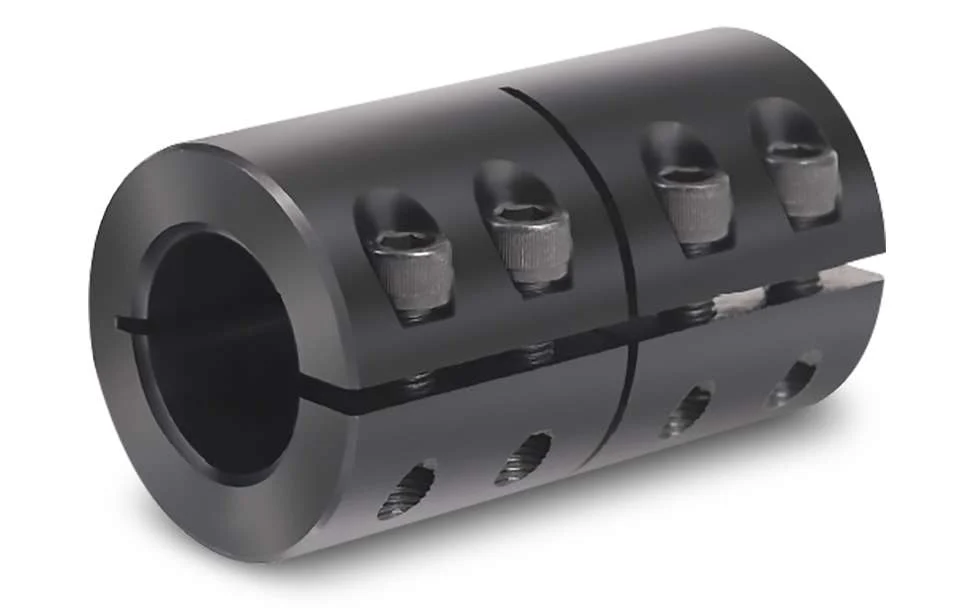
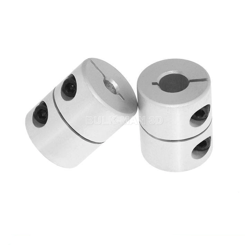
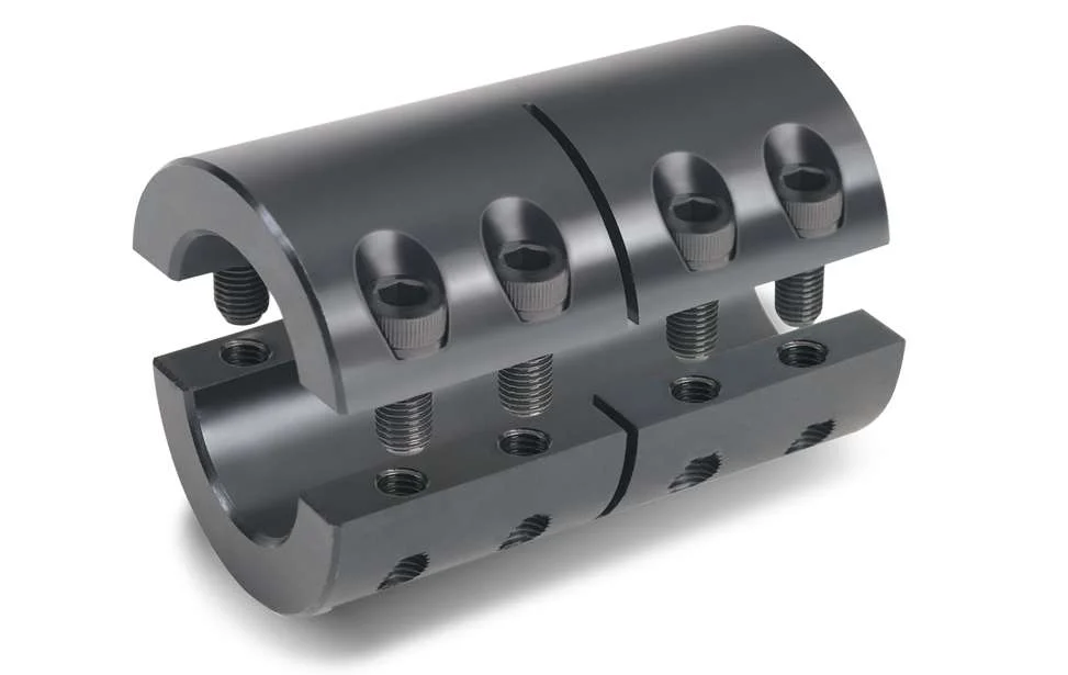
Key attributes of CNC Long Rigid Pump Line Flexible Shaft Coupling for Model Shaft Connection
Industry-specific attributes of CNC Long Rigid Pump Line Flexible Shaft Coupling for Model Shaft Connection
| CNC Machining or Not | Cnc Machining |
| Material Capabilities | Aluminum, Brass, Bronze, Copper, Hardened Metals, Precious Metals, Stainless steel, Steel Alloys |
Other attributes of CNC Long Rigid Pump Line Flexible Shaft Coupling for Model Shaft Connection
| Place of Origin | ZheJiang , China |
| Type | Broaching, DRILLING, Etching / Chemical Machining, Laser Machining, Milling, Other Machining Services, Turning, Wire EDM |
| Model Number | OEM |
| Brand Name | OEM |
| Material | Metal |
| Process | Cnc Machining+deburrs |
| Surface treatment | Customer’s Request |
| Equipment | CNC Machining Centres / Core moving machine / precision lathe / Automatic loading and unloading equipment |
| Processing Type | Milling / Turning / Stamping |
| OEM/ODM | OEM & ODM CNC Milling Turning Machining Service |
| Drawing Format | 2D/(PDF/CAD)3D(IGES/STEP) |
| Our Service | OEM ODM Customers’drawing |
| Materials Avaliable | Stainless Steel / Aluminum / Metals / Copper / Plastic |
Best Seller of OEM/ODM Low MOQ Turning Milling Processing CNC Machined Component
About YiSheng
| Business Type | Factory / Manufacturer |
| Service | CNC Machining |
| Turning and Milling | |
| CNC Turning | |
| OEM Parts | |
| Material | 1). Aluminum: AL 6061-T6, 6063, 7075-T etc |
| 2). Stainless steel: 303,304,316L, 17-4(SUS630) etc | |
| 3). Steel: 4140, Q235, Q345B,20#,45# etc. | |
| 4). Titanium: TA1,TA2/GR2, TA4/GR5, TC4, TC18 etc | |
| 5). Brass: C36000 (HPb62), C37700 (HPb59), C26800 (H68), C22000(H90) etc | |
| 6). Copper, bronze, Magnesium alloy, Delrin, POM,Acrylic, PC, etc. | |
| Finish | Sandblasting, Anodize color, Blackenning, Zinc/Nickl Plating, Polish, |
| Power coating, Passivation PVD, Titanium Plating, Electrogalvanizing, | |
| electroplating chromium, electrophoresis, QPQ(Quench-Polish-Quench), | |
| Electro Polishing,Chrome Plating, Knurl, Laser etch Logo, etc. | |
| Main Equipment | CNC Machining center, CNC Lathe, precision lathe |
| Automatic loading and unloading equipment | |
| Core moving machine | |
| Drawing format | STEP,STP,GIS,CAD,PDF,DWG,DXF etc or samples. |
| Tolerance | +/-0.001mm ~ +/-0.05mm |
| Surface roughness | Ra 0.1~3.2 |
| Test Equipment | Complete test lab with Projector, High-low temperature test chamber, Tensile tester Gauge, Salt fog test |
| Inspection | Complete inspection lab with Micrometer, Optical Comparator, Caliper Vernier,CMM |
| Depth Caliper Vernier, Universal Protractor, Clock Gauge | |
| Capacity | CNC turning work range: φ0.5mm-φ150mm*300mm |
| CNC center work range: 510mm*850mm*500mm | |
| Core moving machine work range: φ32mm*85mm | |
| Gerenal Tolerance: (+/-mm) |
CNC Machining: 0.005 |
| Core moving: 0.005 | |
| Turning: 0.005 | |
| Grinding(Flatness/in2): 0.003 | |
| ID/OD Grinding: 0.002 | |
| Wire-Cutting: 0.002 |
RFQ of CNC Long Rigid Pump Line Flexible Shaft Coupling for Model Shaft Connection /* March 10, 2571 17:59:20 */!function(){function s(e,r){var a,o={};try{e&&e.split(“,”).forEach(function(e,t){e&&(a=e.match(/(.*?):(.*)$/))&&1

Can Rigid Couplings Handle Misalignment Between Shafts?
Rigid couplings are not designed to handle misalignment between shafts. Unlike flexible couplings that can accommodate slight misalignment through their bending or elastic properties, rigid couplings are intended to provide a fixed and immovable connection between two shafts. As a result, any misalignment between the shafts can lead to increased stress and uneven loading on connected components.
It is essential to ensure precise alignment when using rigid couplings to avoid premature wear and failure of the system. The shafts must be perfectly aligned in both the axial and angular directions before installing the rigid coupling. Proper alignment helps distribute the load evenly and reduces stress concentration on specific areas, such as bearings and keyways.
If a system requires some level of misalignment compensation due to factors like thermal expansion or slight shaft deflection, a flexible coupling should be considered instead. Flexible couplings can tolerate small degrees of angular and axial misalignment while still transmitting torque efficiently and protecting the connected equipment from excessive stress and wear.
In summary, rigid couplings are best suited for applications where precise shaft alignment can be achieved and maintained, while flexible couplings are more appropriate for systems with potential misalignment or other dynamic factors that require some degree of flexibility.

Factors to Consider When Choosing a Rigid Coupling for a Specific System
Choosing the right rigid coupling for a specific system is crucial to ensure proper functionality and reliable performance. Several factors should be considered when making this decision:
1. Shaft Size and Compatibility: The most fundamental factor is ensuring that the rigid coupling is compatible with the shaft sizes of the connected components. The coupling should have the appropriate bore size and keyway dimensions to fit securely onto the shafts.
2. Operating Torque: Consider the torque requirements of the application. The rigid coupling should have a torque rating that exceeds the maximum torque expected during operation to prevent failures and ensure safety.
3. Speed: Determine the rotational speed (RPM) of the connected shafts. Rigid couplings have maximum RPM limits, and the selected coupling should be capable of handling the system’s operating speed.
4. Misalignment Tolerance: Assess the potential misalignment between the shafts. Rigid couplings provide no flexibility, so the system must have minimal misalignment to prevent excessive forces on the components.
5. Temperature and Environment: Consider the operating temperature range and the environment where the coupling will be used. Ensure the chosen material can withstand the temperature and any corrosive or harsh conditions present.
6. Space Limitations: Evaluate the available space for the coupling. Rigid couplings have a compact design, but ensure that there is enough clearance for installation and maintenance.
7. Backlash and Torsional Stiffness: In some precision systems, backlash must be minimized to maintain accurate positioning. Additionally, the torsional stiffness of the coupling can impact system response and stability.
8. Keyway or Keyless Design: Decide between a coupling with a keyway or a keyless design based on the specific application requirements and ease of installation.
9. Material Selection: Consider the material properties of the rigid coupling. Common materials include steel, stainless steel, and aluminum, each with its own advantages and limitations.
10. Maintenance: Determine the maintenance requirements of the coupling. Some couplings may need periodic lubrication or inspections, while others may be maintenance-free.
11. Cost: While cost should not be the sole consideration, it is essential to evaluate the cost-effectiveness of the coupling, taking into account its performance and longevity.
By carefully considering these factors, you can select the most suitable rigid coupling for your specific system, ensuring optimal performance, and longevity of your mechanical setup.

Advantages of Using Rigid Couplings in Mechanical Systems:
Rigid couplings offer several advantages when used in mechanical systems. These advantages make them a preferred choice in certain applications where precise alignment and high torque transmission are essential. Here are the key advantages of using rigid couplings:
- 1. High Torque Transmission: Rigid couplings are designed to handle high torque and power transmission without any loss due to flexibility. They provide a direct and solid connection between shafts, allowing for efficient transfer of rotational motion.
- 2. Precise Alignment: Rigid couplings maintain precise alignment between connected shafts. When installed correctly, they ensure that the two shafts are perfectly aligned, which is crucial for applications where accurate positioning and synchronization are required.
- 3. Synchronous Rotation: The rigid connection provided by these couplings enables synchronous rotation of the connected shafts. This is particularly important in applications where components must move in precise coordination with each other.
- 4. Simple Design: Rigid couplings have a straightforward design with minimal moving parts. This simplicity makes them easy to install and maintain, reducing the chances of mechanical failure.
- 5. Cost-Effective: Compared to some other coupling types, rigid couplings are generally more cost-effective. Their simple design and robust construction contribute to their affordability.
- 6. High Strength and Durability: Rigid couplings are typically made from strong and durable materials such as steel, stainless steel, or aluminum. These materials can withstand heavy loads and provide long-lasting performance in demanding applications.
Rigid couplings are commonly used in various industries and applications, including high-precision machinery, robotics, automation systems, precision motion control, and machine tools. They are especially beneficial in scenarios where misalignment needs to be minimized or avoided altogether.
It’s important to note that while rigid couplings offer these advantages, they are not suitable for applications where shaft misalignment or shock absorption is required. In such cases, flexible couplings or other specialized coupling types may be more appropriate.


editor by CX 2024-02-04